|
|
TriTools.com |
|
|
|
|
Visual CADD™ Tips & Tricks |
Tips & Tricks is a new feature on the TriTools and Visual CADD™ web site to help users get the most from Visual CADD™ by learning about new features, helpful tips, and add-on tools. The TriTools team will be periodically adding new topics, so please check back from time to time to see what is new.
We invite users and developers to submit their suggestions, tips, scripts, add-on tools, or other helpful ideas for inclusion on the Tips & Tricks pages.
Contents
Text Keywords
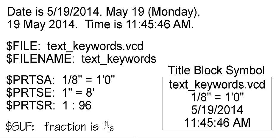
Visual CADD™ supports text keywords for which certain drawing data or values are substituted for screen display and printing. The supported text keywords include current date and/or time in a variety of formats, drawing file name and/or path, print scales in architectural, engineering, or ratio formats, and single unit fractions of the type usually seen in fractional dimensions. The text keywords can be placed into any text kinds of entities, such as text, leaders, or dimension overwrite, prefix, and suffix strings, including within symbols. Text keywords can be very useful in title blocks to automatically display time stamps, file names, and print scales.
The complete list of text keywords and their usage are provided in the Visual CADD™ help file. Open the help file by using menu >Help>Visual CADD Help then search for 'keyword' under the Search tab.
Sample Download
Below is a link to download a sample drawing using text keywords as shown above.
|
|
Text Keywords Sample - Download the Text Keywords sample drawing. Please note, this feature requires Visual CADD™ v7.0.0 or later. |
Latitude-Longitude Import
Visual CADD™ can import or convert data from latitude-longitude to easting-northing (x-y coordinates) in several ways, such as: (1) Use ImportXML/XIX to import a GPX file; (2) Draw with latitude-longitude degree coordinates then convert with a VBScript or other simple add-on tool; or (3) Programatically using the API or ActiveX/COM. The first two techniques are described below.
Import GPX
Many surveying or GPS packages can produce data files known as GPX files which contain latitude-longitude coordinates. A GPX file is a special kind of XML file and Visual CADD™ can import XML files. Visual CADD™ can use an XSLT file (Extensible Stylesheet Language Transformation) to help change from the GPX format to the XML format required by Visual CADD™. Drawing plats and other drafting purposes usually require data be in x-y coordinates with ordinary distance units such as meters or feet, called easting-northing in geographic contexts. The transformation from latitude-longitude to easting-northing can be part of the XSLT file. Lastly, the transformation from latitude-longitude to easting-northing relies upon standardized coordinate reference systems, such as a general purpose Universal Transverse Mercator (UTM) projection or more specialized and localized coordinate reference systems in general use or mandated by various country's and state's laws. Visual CADD™ supports over 3500 coordinate reference systems worldwide.
- Use the EPSG Data Browser together with the latitude-longitude of your data and the projection used to create your data to find the coordinate reference system code (CRS code). The EPSG Data Browser is located in the same folder where you installed Visual CADD™ v7, usually C:\Program Files (x86)\TriTools Partners\Visual CADD 7\Programs\EPSGDataBrowser.exe. The sample below for data around 41 N. latitude, 112 W. longitude uses WGS 84 / UTM zone 12N, which is CRS code 32612.
- Edit the XSLT file C:\Users\Public\Documents\Visual CADD 7\Transforms\gpx_import.xslt to use the desired CRS code. The sample below provides a file C:\Users\Public\Documents\Visual CADD 7\Transforms\gpx_import_CRS_32612.xslt using the 32612 code.
- In Visual CADD™, start the ImportXML tool using the shortcut XIX or the menu >File>Import>XML Files. Click on the Options button, check Transform 1, and use the browse button to choose the C:\Users\Public\Documents\Visual CADD 7\Transforms\gpx_import_CRS_32612.xslt or the one you edited. Click OK when done.
- Back in the Import XML dialog, choose the GPX or XML file you wish to import. The sample below imports the file \My Documents\Visual CADD 7\Drawings\LatLon_Example.gpx.
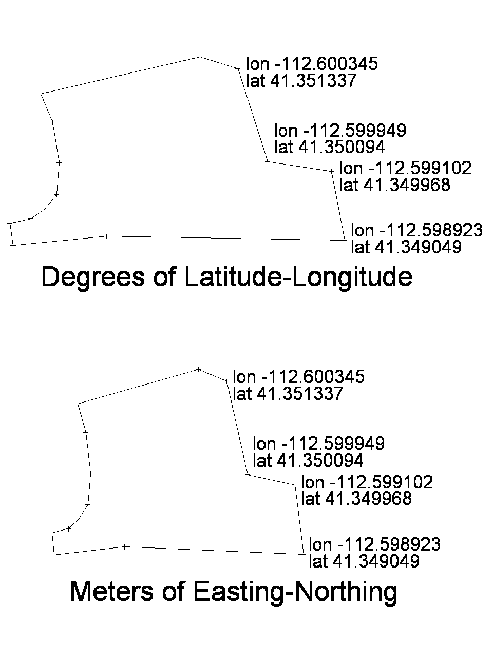
- Using the sample, the import will contain the data points shown in the bottom half of the image to the right. The sample GPX does not include any lines or text. You may then connect points with property or other reference lines, add labels and dimensions, and draw any other required details.
Draw with Latitude-Longitude then Convert
You may also draw in Visual CADD™ using latitude-longitude degree measurements as if they were ordinary distance measurements, using longitude as the x-coordinate and latitude as the y-coordinate. Please note that drawing in this way with latitude-longitude degree measurements does not produce an accurate representation of true relative distances due to the curvature of the earth. However, once drawn in this way or perhaps imported from a DXF file containing latitude-longitude degree measurements, Visual CADD™ can convert the drawing to accurate easting-northing, x-y coordinates using a simple VBScript or similar add-on tool.
- As described above, use the EPSG Data Browser together with the latitude-longitude of your data and the projection used to create your data to find the coordinate reference system code (CRS code).
- Create or edit a script to use the desired CRS code. The sample below provides a custom command file C:\Program Files (x86)\TriTools Partners\Visual CADD 7\Addons\LatLon\CmdExt.vcdef using the 32612 code. The custom command runs the sample VBScript C:\Users\Public\Documents\Visual CADD 7\Macros\LatLon.vbs. You may use the CmdExt.vcdef and LatLon.vbs as the starting point for your own custom commands and scripts.
- In Visual CADD™, draw, import, or open a drawing which contains your data drawn using latitude-longitude degree measurements. The sample drawing \My Documents\Visual CADD 7\Drawings\LatLon_Example.vcd is shown in the top half of the image to the right.
- Run your script to convert from latitude-longitude to easting-northing. The sample below creates a shortcut XXE so you may type XXE to convert the sample drawing. The sample will convert the latitude-longitude drawing to easting-northing as shown in the bottom half of the image to the right.
- You may then draw any other required details using ordinary distance measurements.
A Note on Accuracy
The accuracy of civilian DGPS is about 10cm at best. One minute (1/60th degree) of longitude at the equator is very close to 1 nautical mile. With a little calculation, you will find that 0.000001 degree of longitude at the equator is approximately 11cm. So, the accuracy of civilian DGPS is very close to 0.000001 degree of longitude at the equator. Therefore, when using DGPS data there is no advantage to using more than 6 decimal place accuracy for latitude-longitude measured in degrees. Any more than 6 decimal places would usually give a false sense of accuracy.
Sample Download
Below is a link to download and install sample files to illustrate latitude-longitude import, including GPX and VCD files containing latitude-longitude data, XSLT transformation file for XML import, VBScript for conversion of existing VCD, and CmdExt.vcdef file to create the custom command.
|
|
Lat-Lon Tools - Download the Latitude-Longitude Tool installer. Please note, this tool as written requires Visual CADD™ v7.0.0 or later. |
Surveyor Bearing Labels
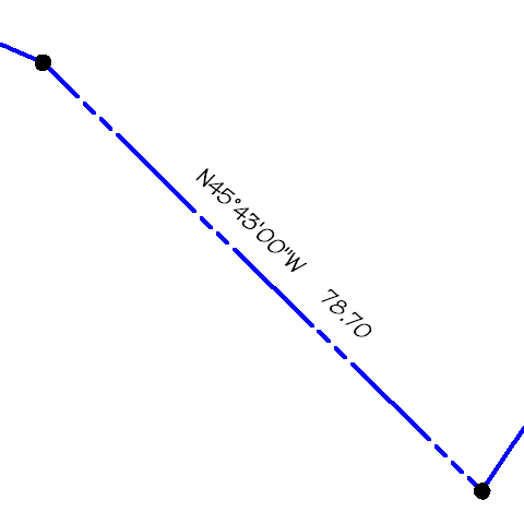
Visual CADD™ supports placing surveyor bearings in a drawing using the linear dimension tool, DimLin/DL. Before placing the bearing, you would set the necessary settings using >Utilities>Settings, primarily the tree branches under >Drawing: >Numeric, >Dimensions>Settings, and >Dimensions>Text. The shortcuts to those dialogs are TBN, TBD, and TBX, respectively. Essential settings are on TBX where you would set Distance/Angle Display to be one of the choices for an angle in a linear dimension and on TBN where you would set the surveyor format settings. Then you place the dimension using >Draw>Dimension>Linear Dimension or DimLin/DL.
The necessary settings can be set in a number of ways: manually in the settings dialogs, a custom command defined in Script Assign, running a VBScript, loading previously saved styles, using an add-on tool, and other ways.
Sample Download
Below is a link to download and install a VBScript to simplify placing surveyor bearings in a drawing. This sample tool will place your bearing label then return all settings to their original so that you can place ordinary linear dimensions as before. After installing, you may optionally edit the VBScript to make changes specific to your needs, such as the decimal places on the distances.
|
|
Bearing Label Tool - Download the Bearing Label Tool installer. Please note, this tool as written requires Visual CADD™ v7.0.1 or later. Depending upon specific needs, the VBScript can be modified to work with earlier versions. |
|
|
Home | VisualCADD.net | Purchase | Shopping Cart | Help Desk | Contact Copyright © 2023 Gold Run Partners, Inc. dba TriTools Partners. All Rights Reserved. |
|