|
Visual CADD™ v6 Features
|
The list below describes new features in Visual CADD™ v6.
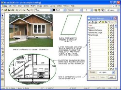
Click on the thumbnail at right to open a larger image that will
give you a better idea of what v6 looks like.
It shows several of the features that are described on this page,
including the new Image command, Skew command, enhancements
to Reference Frames, new Layer commands and improvements to
the Layer Manager dialog and Layer Group Interface.
What's New in v6
-
 AutoPan command with the middle mouse button.
The AutoPan option lets you
hold down the scroll wheel button and drag the drawing around on
the screen (it is also a native command with the keyboard
shortcut AA, repeatable by pressing the spacebar).
-
DWG/DXF
import/export now supports newer formats.
You can import files
up to DWG 2012 in Visual CADD™ v6.
And export to 6 different DWG
versions including 2012.
-
All files not
in the Visual CADD™ (vcd) format are now opened and saved via
Import/Export menus.
To save a file in one of the different CADD
formats supported by Visual CADD™ such as AutoCAD or Generic
CADD, use the File>Export>CADD Files menu item.
To import
a file, use the File>Import>CADD Files menu item.
Note
that both are a new v6 feature.
In previous versions, AutoCAD
and Generic CADD files were opened and saved from the FileOpen
and FileSave menu item.
-
Insert
Graphic images into Visual CADD™ v6.
GIF, BMP, JPEG, TIFF, and
other raster files can be added to Visual CADD™ via the IMAGE
command on the Draw menu.
They can be moved, scaled, copied etc
after they are placed in the drawing.
Images can be either
embedded or linked to the drawing.
-
XML Files are
an important new feature in Visual CADD™ v6.
You can now import and export XML data files.
They offer
powerful new options for manipulating data in v6.
XML files are also now the default file type for Customizing
VCADD files.
-
There are new
Features for commands on the Print menu.
The Print dialog has been revised to make it easier to select a
different printer or page size.
And you can now add a Watermark
to a print (as well as a PDF), and in both cases select the
density of the watermark to make it darker or lighter under the
objects in your drawing.
A new Save All (FL) command lets you
save all open drawings.
-
Reference
Frames have improved features.
Reference frames can now be self referencing.
You can create a reference
frame in a drawing file and include parts of the same drawing inside the reference frame.
Reference Frames can now have
an ellipse rather than rectangular border.
-
The Settings
dialog has a new look that better defines which settings are
global and which are drawing specific.
Some Visual CADD™ settings apply to all drawings open in the
program (the cursor size is one example), while others are saved
with each drawing and are specific to that file.
The new dialog
better defines the difference between Global and Drawing
specific settings.
-
New Settings
dialogs for Leader Text, Symbols and Font Manager.
The additional dialogs make it easier to manage these settings.
Leader Text shows new text alignment options.
Symbol dialog
organizes symbol and attribute settings in one place.
And the
new Font Manager allows you to list only certain combinations of
fonts, and has features for font substitution.
-
Enhanced
Assign Script dialog with new features.
The dialog now has separate tabs for Scripts, Custom Shortcuts
and Custom Commands.
You can change keyboard shortcuts for
Native commands in the interface, without having to edit a
separate file.
And you can now add bitmap location for Custom
Commands without having to edit a separate file.
-
Bearing Tools
removed (they will still be available in our toolkit addon).
Visual CADD™ now
supports these former tools internally but with more useful
options.
Polar input is simplified.
All the old Bearings settings
commands are available on the Numeric dialog.
The new Multiple
Dimension command replaces the Bearing Label command.
The next
few entries below will expand on this.
More New Features
-
Enhanced polar coordinate entry now recognizes polar input
without needing to use a comma, and also surveyor input without
the less-than symbol.
Inputs of "1,<45", "1<45",
"1,<N45W", "1,N45W" and "1<N45W" all now work for polar
input.
-
On the Angular
Options dropdown on the Numeric dialog you now have several new
choices including Surveyor.
Coupled with the ability to
set base angle as described below and new input features
mentioned above, it opens up new options for quickly creating
site and plot plans and other types of drawings.
-
New Base Angle setting on Numeric tab
is saved with each
drawing.
The default setting of 0 degrees at 3 o'clock can be
changed to any angle, and the coordinates in the status bar will
reflect this.
Replaces and enhances the old Bearing Settings
dialog.
-
Multiple Dimension (MM) command added to quickly add linear
dimensions to selected objects.
Replaces the old Bearing Labels
command.
-
PDF Export command now supports
an option to save individual Layers when creating
the PDF.
Many PDF Reader will support individual layers.
-
SaveAll command on File menu saves all open drawings.
-
MultiLine is a
new entity type in v6.
This means that rather than a series of
single lines, multiline is placed as a single object.
Editing a
multiline affects all line segments.
If you prefer the older
placement of a series of single lines this is still an option.
-
Added .gif file format to the
existing Image Export command.
-
New Skew (KW)
command to modify objects.
Very useful with rectangles and
polygons to quickly change their shape.
Located on the Modify
menu.
-
Select Modified (SU) command selects new objects created by the
copy commands.
-
File Compression
option to reduce the size of the Visual CADD™ file (Files using this option are not
backward compatible).
-
File Encryption
option for password protection of a Visual CADD™ file (Files using this option are
not backward compatible).
-
New Run Macro command to support the Macro language, which has
much more power and flexibility than the current scripting
feature.
There are several examples in the Macros folder.
-
Customizable
files (menus, toolbars etc) are now in the XML format.
This
provides a structured file with tags that will make it easier to
understand each line in the file.
The older TXT files showed a
value but with no reference to what it was.
-
Version 6 has a
new Configuration Editor to create or edit customizable XML
files.
If you have an alternate editor you wish to use, there is
also a new command to set a different configuration editor.
-
Hatches now have individual
properties.
Previously you could set a color while placing a
hatch, and change the layer and/or color when editing a hatch.
Now you can control layer, color, linetype and linewidth both
when placing or editing a hatch.
-
Leader parts now feature individual
properties.
For example, you can set different color, linetype
or width for arrows, lines and text.
-
Text now has individual properties.
Previously you could set a
text layer and a color.
Now you can also specify a linetype and
lineweight.
-
Tab stops for text and also for leaders.
-
Leader shoulders and text can now be set to any angle.
-
Leader text now has several options for a border around it.
-
New setting for Radial Dimensions for alternate arrow location
on far side of object.
-
New options for the display of dimension text strings containing
both distance and angle.
-
Added $PI(), $ACS() (acos) and $ASN() (asin) math functions to
the input parsing.
 AutoPan command with the middle mouse button.
The AutoPan option lets you
hold down the scroll wheel button and drag the drawing around on
the screen (it is also a native command with the keyboard
shortcut AA, repeatable by pressing the spacebar).

